SECTION
ACME ELECTRIC
•
MILWAUKEE, WI
•
800.334.5214
•
acmetransformer.com
47
SECTION
DRIVE ISOLATION TRANSFORMERS
For Information On The Following,
Please Contact The Factory
1.
Transformers rated primary 230 volts delta, secondary 460Y/266 volts.
2.
Low temperature rise units using class 220°C insulation with
either 115°C or 80°C rise operating temperature.
3.
Totally enclosed non-ventilated units.
Windings, Terminations and Construction
①
Optional wall mounting kits – part # PL 79911 refer to Page 133.
②
Optional wall mounting kits – part # PL 79912 refer to Page 133.
The number in ( )’s following the catalog number is the electrical wiring diagram number beginning on page 155.
GROUP E
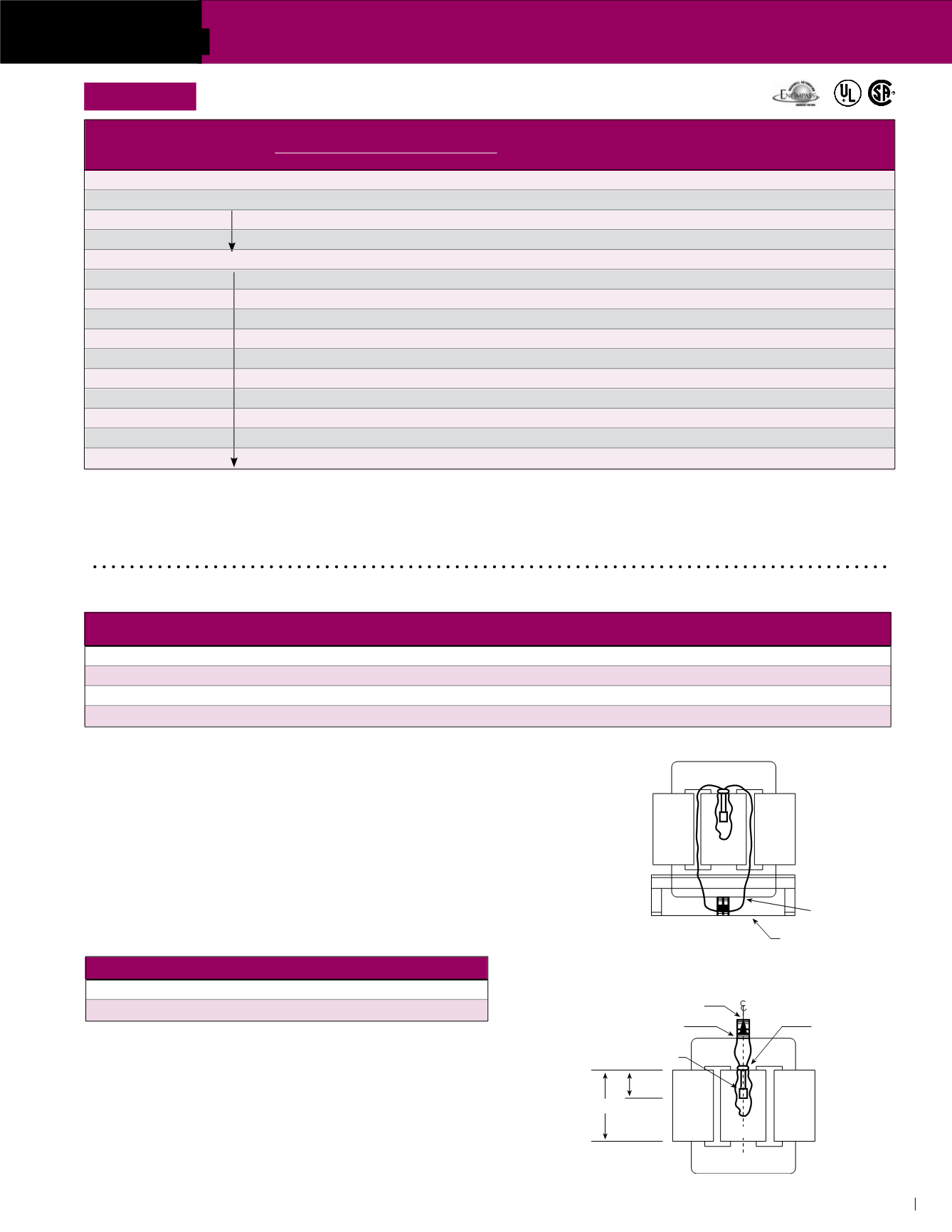
Figure 1
Figure 2
COIL 1 COIL 2 COIL 3
CORE
BOTTOM OF CASE
COIL 1
COIL 3
THERMAL SWITCH
.625 (1.6 cm) H DIA.
EPOXY-RING
CORE
EPOXY LAYER
TERMINAL BLOCK
H
.5H
(1.3 cm)
COIL 2
Thermal Switch Kit - PL-79900
Acme Thermal Switch Kits are designed for use with single and three phase
drive isolation and distribution transformers. Thermal switch kits are available
for a one or three sensor system.
Thermal sensors can be field installed in the transformer winding ducts to detect
abnormal temperatures. The thermal sensors are a normally closed contact
that opens at 200°C ± 10°C and has a current capacity of 5 amps @ 120V or
2.5 amps @ 240V. This contact can activate any number of different types of
alarms or mechanisms that could warn of a potential failure.
kVA
Mounting Position
Illustration
27.0-118.0
Bottom of the case
Figure 1
145-750
Top flange of the core bracket
Figure 2
Primary
Secondary
Insulation
Construction
kVA
Winding
Winding
System
Termination
Enclosure
Core
7.5
CU wire
CU wire
180°C
CU wire
Epoxy encapsulated
Wound/distributed gap
11-20
AL foil
AL foil
180°C
CU wire
Epoxy encapsulated
Wound/distributed gap
27-220
AL foil
AL foil
220°C
CU bus
Ventilated
Wound/distributed gap
275-660
AL foil
AL foil
220°C
AL bus
Ventilated
Butt stacked/Step lap
PRIMARY 230 Delta
APPROX. DIMENSIONS
APPROX.
TYPE MTG.
Weather
kVA SECONDARY 230Y/133
Inches (Cm.)
SHIP WEIGHT W – Wall
Knockouts
Shield DIM.
CATALOG NO.
Height
Width
Depth
Lbs. (Kg.)
F – Floor
Inches (Cm.)
P/N
Drawing
7.5
DTFA72S (62)
15.21 (38.6)
19.25 (48.9)
7.37 (18.7)
180 (81.6)
W
NA
NA
F
11.0
DTFA0112S (62)
18.86 (48.0)
20.30 (51.6)
9.03 (22.9)
265 (120.0)
F
①
NA
NA
I
14.0
DTFA0142S
18.86 (48.0)
20.30 (51.6)
9.03 (22.9)
265 (120.0)
F
①
NA
NA
I
20.0
DTFA0202S
20.77 (52.8)
20.94 (53.2)
10.18 (25.9)
435 (197.0)
F
①
NA
NA
I
27.0
DTFA0274S (59)
25.48 (64.8)
24.39 (62.0)
19.40 (49.3)
302 (137.0)
F
②
NA
WSA1
E
34.0
DTFA0344S
25.48 (64.8)
24.39 (62.0)
19.40 (49.3)
330 (150.0)
F
②
NA
WSA1
E
40.0
DTFA0404S
25.48 (64.8)
24.39 (62.0)
19.40 (49.3)
370 (168.0)
F
②
NA
WSA1
E
51.0
DTFA0514S
29.40 (74.7)
28.15 (71.5)
22.40 (56.9)
375 (170.0)
F
②
NA
WSA2
E
63.0
DTFA0634S
29.40 (74.7)
28.15 (71.5)
22.40 (56.9)
495 (225.0)
F
②
NA
WSA2
E
75.0
DTFA0754S
29.40 (74.7)
28.15 (71.5)
22.40 (56.9)
525 (238.0)
F
②
NA
WSA2
E
93.0
DTFA0934S
35.40 (89.9)
31.90 (81.0)
26.90 (68.3)
685 (311.0)
F
NA
WSA3
E
118.0
DTFA01184S
35.40 (89.9)
31.90 (81.0)
26.90 (68.3)
710 (322.0)
F
NA
WSA3
E
145.0
DTFA01454S
41.52 (105.5)
32.90 (83.6)
29.90 (75.9)
980 (445.0)
F
NA
WSA4
E
175.0
DTFA01754S
41.52 (105.5)
32.90 (83.6)
29.90 (75.9)
1110 (504.0)
F
NA
WSA4
E
220.0
DTFA02204S
41.52 (105.5)
32.90 (83.6)
29.90 (75.9)
1120 (508.0)
F
NA
WSA4
E
DRIVE ISOLATION DESIGN FIGURES
(Refer to pg 122)


