
B u c k - B o o s t T r a n s f o r m e r s
120
toll free 800.334.5214 ACME ELECTRIC |
hubbell-acmeelectric.comQUESTIONS AND ANSWERS ABOUT BUCK-BOOST TRANSFORMERS
1. What is a buck-boost transformer?
Buck-boost transformers are small single phase transformers designed to reduce (buck) or raise (boost) line voltage from 5 -20%.
The most common example is boosting 208 volts to 230 volts, usually to operate a 230 volt motor such as an air-conditioner
compressor, from a 208 volt supply line.
Buck-boosts are a standard type of single phase distribution transformers, with primary voltages of 120, 240 or 480 volts
and secondaries typically of 12, 16, 24, 32 or 48 volts. They are available in sizes ranging from 50 volt amperes to
10 kilo-volt amperes.
Buck-boost transformers are shipped ready to be connected for a number of possible voltage combinations.
2. How does a buck-boost transformer differ from an insulating transformer?
A buck-boost transformer IS an insulating type transformer when it is shipped from the factory. When it is connected at the job
site, a lead wire on the primary is connected to a lead wire on the secondary – thereby changing the transformer’s electrical
characteristics to those of an autotransformer. The primary and secondary windings are no longer “insulated” and secondary
windings are no longer “insulated” and its kVA capacity is greatly increased. Refer to figures 1, 2 and 3.
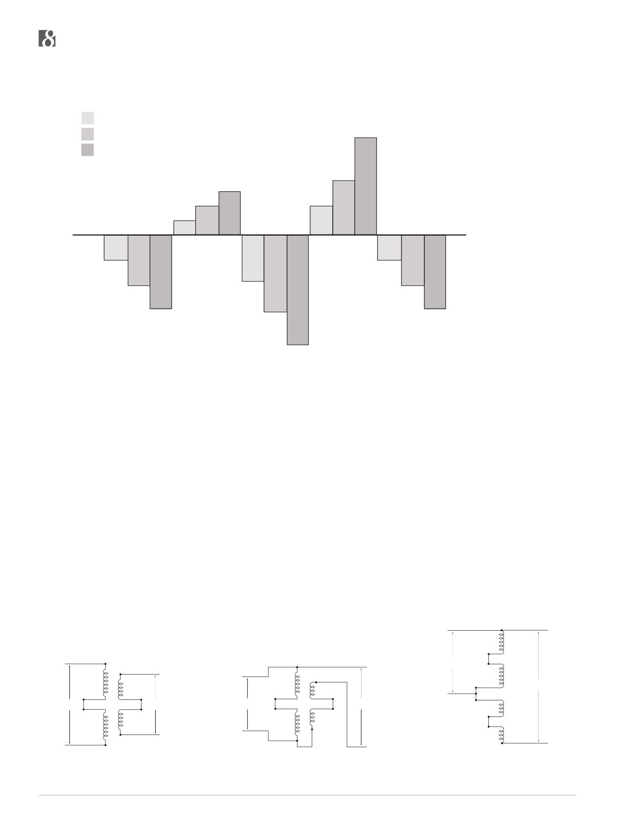
HOW LOW VOLTAGE AFFECTS VARIOUS EQUIPMENT OPERATIONS AND FUNCTIONS
150%
140%
130%
120%
110%
100%
90%
80%
70%
60%
50%
90.5%
81%
72%
105%
111%
117%
84%
70%
57%
111%
123%
138%
90.5%
81%
72%
Increase of Motor Tempera-
ture and Corresponding
Insulation Life Expectancy
Loss
Increase of Motor Winding
Current Requirements in
Induction Motor Loads
Decrease in Motor Torque
Output
Decrease of
Incandescent
Lighting Output
Decrease of Heat Output in
Resistive Heating Loads
= 5% Low Voltage
= 10% Low Voltage
= 15% Low Voltage
X1
X2
X3
X4
OUTPUT
H4
INPUT
H2
H3
H1
Figure 1. Buck-boost transformer connected as a
low voltage insulating transformer (primary and
secondary windings shown series connected).
X1
X2
X3
X4
OUTPUT
H4
INPUT
H2
H3
H1
Figure 2. Same buck-boost transformer
connected as a boosting autotransformer. The
connection from H1 to X4 “converted” the unit to
an autotransformer.
X1
X2
X3
X4
OUTPUT
H4
INPUT
H2
H3
H1
Figure 3. Illustration No. 2 shown with the primary
and secondary windings “straightened”.


