
Accessories
G e n e r a l
217
toll free 800.334.5214 ACME ELECTRIC |
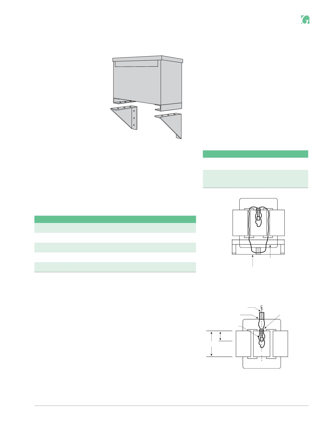
hubbell-acmeelectric.comWALL MOUNTING BRACKET
Required on:
Ventilated Units:
1Ø, 37.5 and 50 kVA
3Ø, 30, 45 and 75 kVA
Catalog Number: PL-79912
Encapsulated Units:
3Ø dit., 11 kVA — 20 kVA
3Ø std. distribution — 15 kVA
Catalog Number: PL-79911
Wall mounting brackets are not
required on:
1Ø units — 25 kVA and below
3Ø units — 9 kVA and below
STANDARD TAPS
The catalog number suffix provides tap information as outlined in chart below:
If the catalog number has no suffix, there are no taps available.
EXAMPLE: T-2-53019-3S
The suffix 3S indicates the unit has two 2.5% (+) ANFC taps and four 2.5%
(–) BNFC taps.
Suffix
Tap Arrangement
– 1S
Two 5% (–) BNFC Taps
– 2S
One 5% (+) ANFC Tap and One 5% (–) BNFC Tap
– 3S
Two 2-1/2% (+) ANFC Taps and Four 2-1/2%(–) BNFC Taps
– 4S
Two 2-1/2% (+) ANFC Taps and Two 2-1/2% (–) BNFC Taps
– 5S
Two 5% (+) ANFC Taps and Two 5% (–) BNFC Taps
Catalog Number: PL-79900
kVA
Mounting Position
Illustration
27.0 – 220.0
Bottom of the case
Figure 1
275.0– 750
Top Flange of the
Core Bracket
Figure 2
THERMAL SWITCH KITS
Acme Thermal Switch Kits are designed for use
withsingle and three phase drive isolation and
distribution transformers. Thermal switch kits are
available for one or three sensor systems.
Thermal sensors can be field or factory installed in
the transformer winding ducts to detect abnormal
temperatures. The thermal sensors are a
normally closed contact that opens at 200°C ±
10°C and has a current capacity of 5 amps @ 120V
or 2.5 amps @ 240V. This contact can activate any
number of different types of alarms or mechanisms
that could warn of a potential failure.
COIL 1
COIL 3
THERMAL SWITCH
.625 (1.6 cm) H DIA.
EPOXY-RING
CORE
EPOXY LAYER
TERMINAL BLOCK
H
.5H
(1.3 cm)
COIL 2
Figure 2
COIL 1 COIL 2 COIL 3
CORE
BOTTOM OF CASE
Figure 1


