
6
75
toll free 800.334.5214 ACME ELECTRIC |
hubbell-acmeelectric.comT A S e r i e s O p e n C o r e a n d C o i l I n d u s t r i a l C o n t r o l T r a n s f o r m e r s
TA SERIES PRIMARY FUSE KITS
Type PL112700 Through PL112705:
Using 2Class CC Dual Element Fuses (not supplied)
Q
Meets NEC Article 450 and UL-508 requirements.
Q
For use with class “CC” fuses.
Q
Eliminates remote mounting of primary overcurrent protection.
Q
Covered by Acme Electric 10-year limited warranty.
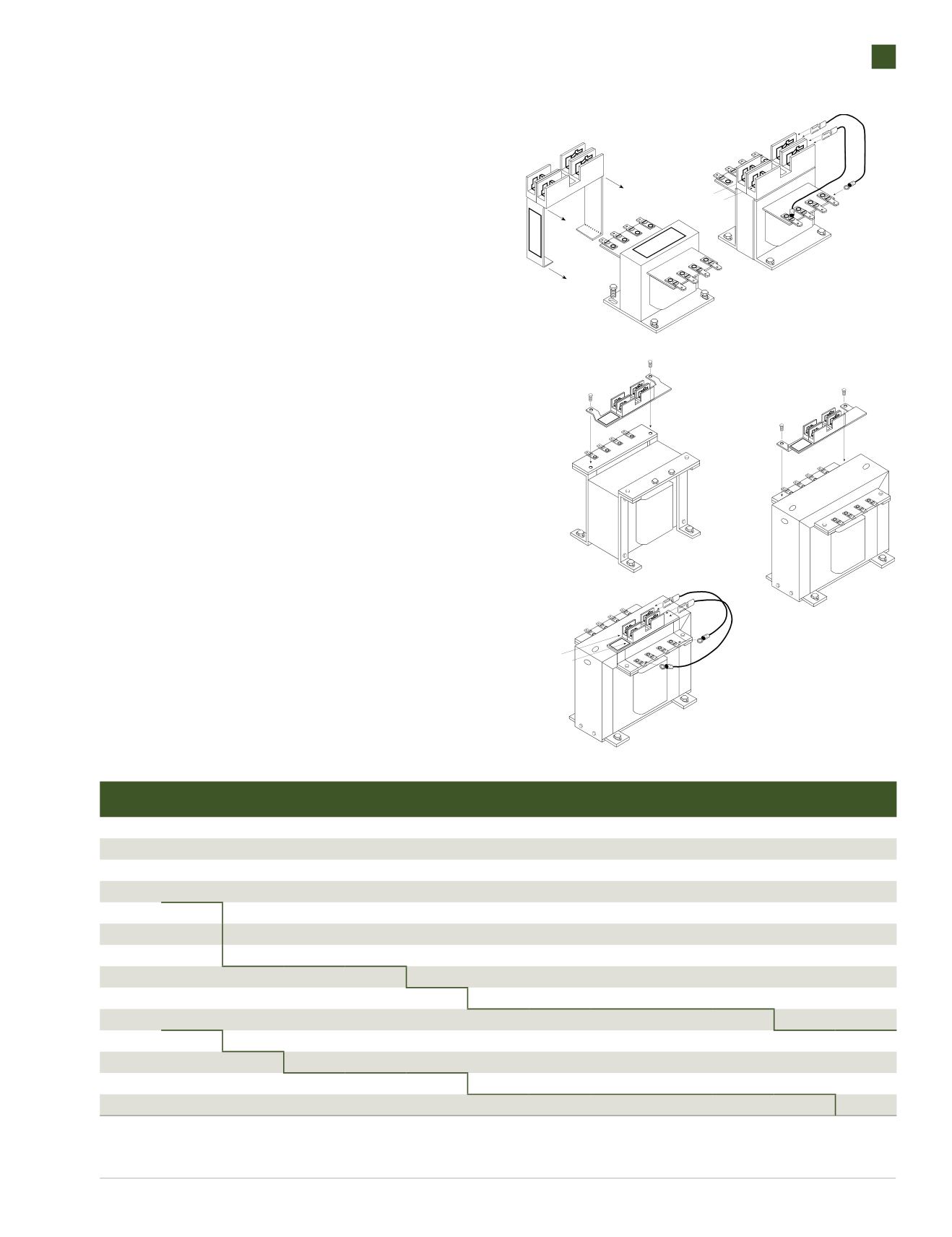
Field installation is fast and easy. Simply loosen the mounting hardware
(Fig. 1), slide the bracket over the transformer and re-tighten the mounting
hardware. Make the proper connections with the factory furnished jumpers
(Fig. 2) and your unit is ready for operation.
INSTRUCTIONS FORTA SERIES PRIMARY FUSE KITS
Type PL112706 Through PL112707: 3000 - 5000 VA
Using 2 Class CC Dual Element Fuses (not supplied)
1. To mount the primary fuse kit bracket, remove the two 1/4”
(.64 cm) sheet metal screws on the terminal panel on the
primary (H side) of the transformer.
2. Place the slots in the fuse kit mounting bracket over the
holes in the terminal and mounting bracket. To secure the
fuse kit, reinsert the two 1/4” (.64 cm) sheet metal screws
and tighten securely.
3. Tighten all mounting screws securely–this will secure the
mounting bracket.
4. Attach the female quick connect of the jumpers supplied
with the fuse kit to male quick connects on the right side of the
fuse blocks—one jumper to each of the blocks.
5. Connect the ring terminal of the jumpers to the appropriate
screw terminals of the transformers primary (H side). Refer to
the transformer name plate for proper terminal connections.
6. Connect primary supply line leads to the screw terminals
on the left side of the block—one line lead to each of the fuse blocks.
Figure 1
Figure 2
PRIMARY FUSE SIZING CHART
①
VA
120V
208V
230V
240V
277V
380V
416V
440V
460V
480V
550V
600V
50
1.2
0.6
0.6
0.6
0.6
0.3
0.3
0.3
0.3
0.3
0.3
0.3
75
1.9
1.0
1.0
1.0
0.8
0.6
0.6
0.6
0.5
0.5
0.4
0.4
100
2.5
1.5
1.3
1.3
1.0
0.8
0.8
0.6
0.6
0.6
0.6
0.5
150
3.8
2.0
2.0
1.9
1.5
1.2
1.2
1.0
1.0
1.0
0.8
0.8
250
3.5
3.5
3.5
3.0
3.0
2.0
1.8
1.8
1.5
1.5
1.4
1.2
300
4.0
4.0
4.0
3.5
3.0
2.5
2.5
2.0
2.0
1.9
1.5
1.5
350
5.0
5.0
4.5
4.0
4.0
2.5
2.5
2.5
2.0
2.0
1.9
1.8
500
7.0
4.0
3.5
3.5
5.5
4.0
3.5
3.5
3.5
3.0
3.0
2.5
750
10.0
6.0
5.5
5.0
4.5
6.0
5.5
5.0
5.0
5.0
4.0
4.0
1000
15.0
8.0
7.0
7.0
6.0
4.5
4.0
3.5
3.5
3.5
5.5
5.0
1500
20.0
12.0
12.0
12.0
10.0
7.0
6.0
6.0
5.5
5.5
5.0
4.5
2000
25.0
12.0
15.0
15.0
12.0
9.0
8.0
8.0
7.5
7.0
6.0
6.0
3000
30.0
20.0
20.0
20.0
15.0
15.0
12.0
12.0
12.0
12.0
10.0
9.0
5000
––
30.0
30.0
30.0
25.0
20.0
15.0
15.0
15.0
15.0
12.0
15.0
①
Fuse size based on time delay class CC fuses.
NOTE: Bold lines indicate changes in the percent of rated current used to calculate fuse sizes in accordance with article 450 of the NEC.
INPUT
SUPPLY
LINE
PRIMARY (HSIDE)
SECONDARY (XSIDE)
PRIMARY (HSIDE)
SECONDARY (XSIDE)
PRIMARY (HSIDE)
INPUT
SUPPLY
LINE
PRIMARY (HSIDE)
SECONDARY (XSIDE)


