
47
toll free 800.334.5214 ACME ELECTRIC |
hubbell-acmeelectric.comSelection Charts
H a r m o n i c M i t i g a t i n g T r a n s f o r m e r s
480 DELTA PRIMARY VOLTS — 208Y/120 SECONDARY VOLTS
kVA Catalog Number
Height
(Inches)(Cm.)
Width
(Inches)(Cm.)
Depth
(Inches)(Cm.)
Weight
(Lbs.)(Kg.)
Mounting Type
(Wall)(Floor)
Weather
Shield
Wiring
Diagrams
Design
Figures
30.0 H3030K0014BCS 25.50 (64.8)
24.39 (61.9)
19.37 (49.2)
360 (163.2)
F
①
WSA1
81
E
45.0 H3045K0014BCS 25.50 (64.8)
24.39 (61.9)
19.37 (49.2)
500 (226.8)
F
①
WSA1
81
E
75.0 H3075K0014BCS 29.41 (74.7)
28.15 (71.5)
22.37 (56.8)
600 (272.2)
F
①
WSA2
81
E
112.5 H3112K0014BCS 35.47 (90.1)
31.90 (81.0)
26.88 (68.2)
938 (425.5)
F
WSA3
81
E
150.0 H3150K0014BCS 41.52 (105.5)
32.90 (83.5)
29.87 (75.9)
1213 (550.2)
F
WSA4
81
E
225.0 H3225K0014BCS 41.52 (105.5)
32.90 (83.5)
29.87 (75.9)
1872 (849.1)
F
WSA4
81
E
Notes: All models are DOE 2016 compliant
Wall mounting brackets are available for these sizes, refer to page 217.
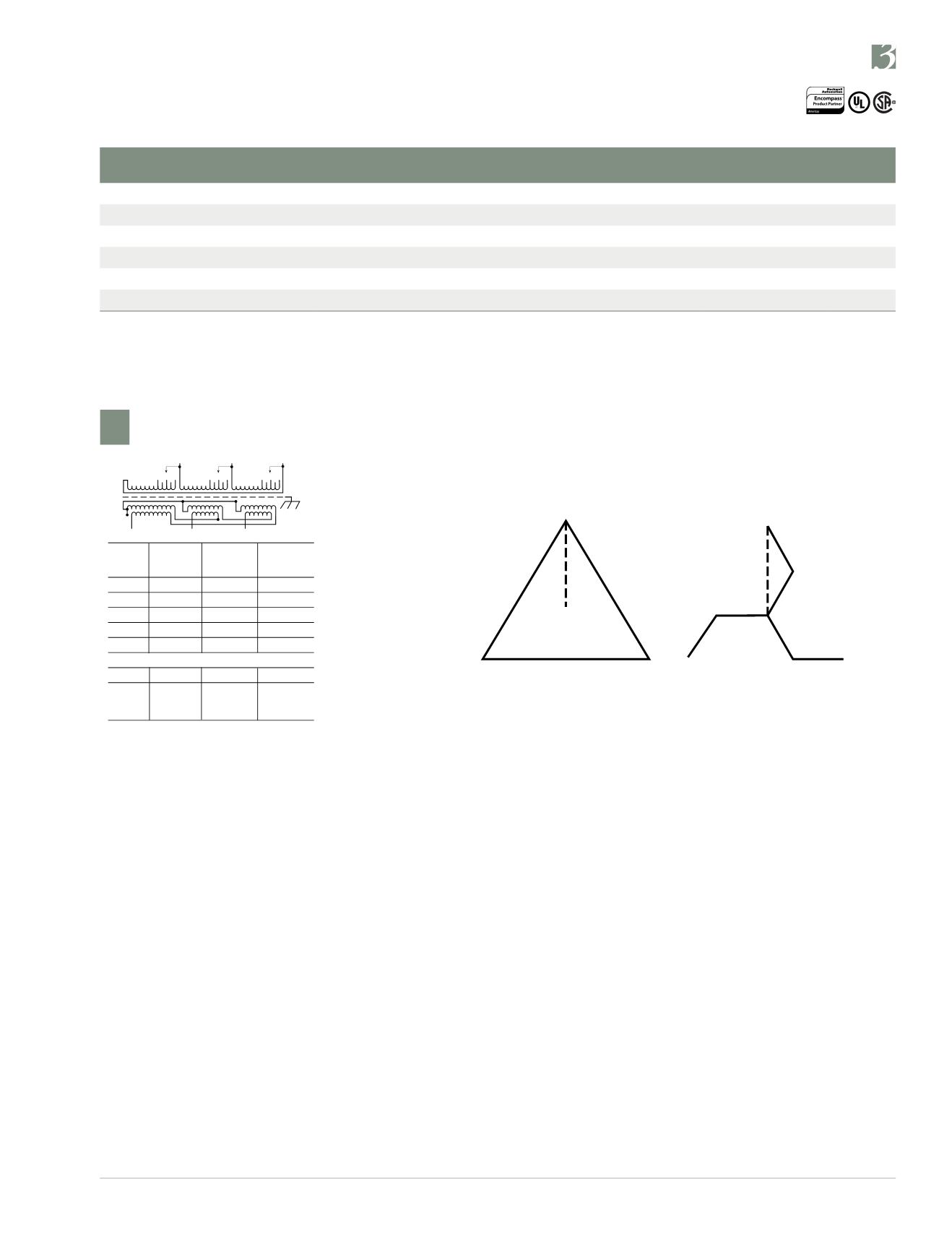
Harmonic Mitigating Transformers Wiring Diagram
Diagram Showing Delta Primary and Zig-Zag Secondary
(Zero degree angular displacement)
Harmonic Mitigating Transformers – How do they work?
They consist of a Delta primary and a Zig-Zag secondary. The Zig-Zag secondary causes a phase shift in the triplen
harmonics, which results in a canceling effect. This prevents the triplen harmonic losses from being coupled back into the
primary and results in cooler operation and increased energy efficiency.
PRIMARY: 480 Volts Delta
SECONDARY: 208Y/120 Volts
TAPS: 2, 2
1
/
2
% ANFC, 2, 2
1
/
2
% BNFC
12345
12345
12345
X3
X2
X1
H1
H2
H3
X0
81
Connect
Connect
Primary
Primary
Inter-
Secondary
Volts
Lines To
Connect
Lines To
504
H1, H2, H3
1
492
H1, H2, H3
2
480
H1, H2, H3
3
468
H1, H2, H3
4
456
H1, H2, H3
5
Secondary Volts
208
X1, X2, X3
120
X1 to X0
1 phase
X2 to X0
X3 to X0
H2
X2
H1
H3 X1
X3
X0
All Wiring Diagrams begin on page 209.


