
P o w e r C o n d i t i o n i n g P r o d u c t s
Selection Charts
158
toll free 800.334.5214 ACME ELECTRIC |
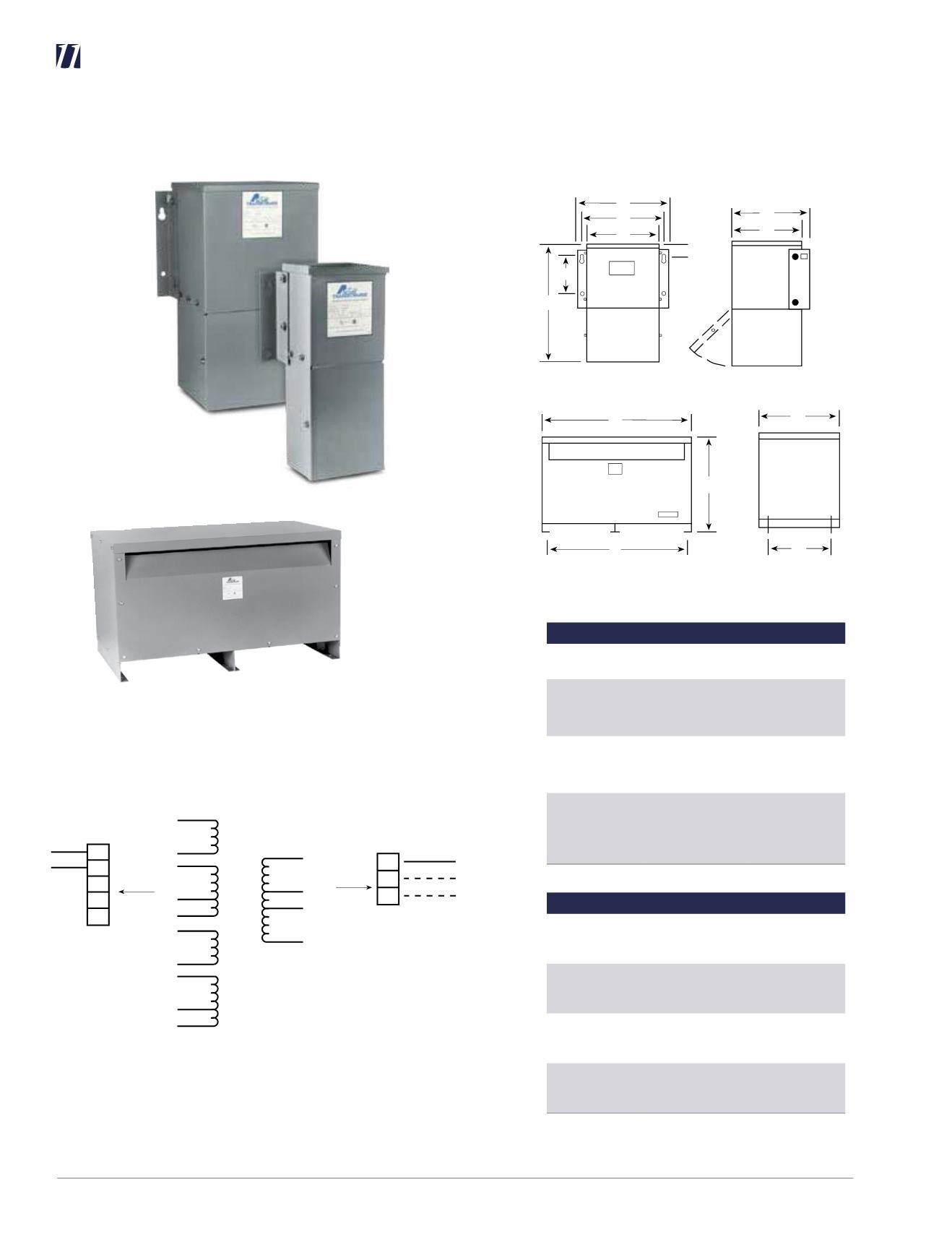
hubbell-acmeelectric.comCONSTANT VOLTAGE REGULATORS DIMENSIONAL DRAWINGS
Figure II and III
A
B
D
E
F
G
J
C
A
E
B
D
C
Front View
Side View
Front View
Side View
Power Line Conditioner
2
F
1
3
H
4
5
6
7
8
G
9
10
11
12
13
14
B
C
D
E
A
INPUT LINE
Input Connections Insulate
Volts
Connect
Isolate
120
1, 3, 6, 8 to A
2, 5, 7, 10 to B
4, 9
208
1, 6 to A
4, 9 to B
2, 3 to C
7, 8 to D
5, 10
240
1, 6 to A
5, 10 to B
2, 3 to C
7, 8 to D
4, 9
480
1 to A
10 to B
2, 3 to C
5, 6 to D
7, 8 to E
4, 9
Output Connections
Volts
Connect
Output Lines To
120
11 to F
12 to G
14 to H
F, G
208
11 to F
12 to G
14 to H
F, G, H
240
11 to F
12 to G
13 to H
F, H
480
11 to F
12 to G
14 to H
F, H
NOTE:
To prevent externally shorting, all leads marked “INSULATE”
must be individually capped with wire nuts or equivalent. Insulate
leads individually!
Figure IV


