
111
toll free 800.307.6702 MASTERVOLT | mastervolt.com MARINCO | marinco.com ANCOR | ancorproducts.com
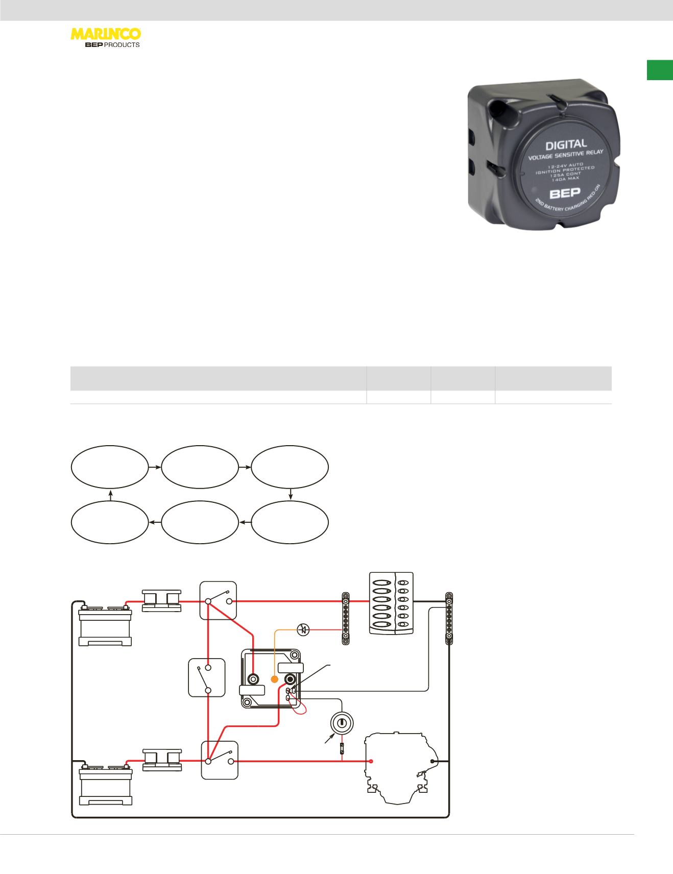
DVSR: Dual Battery Charging Made Easy
The Digital Voltage Sensing Relay (DVSR) provides a highly efficient but inexpensive
solution for automatic charging of a second battery bank. It ensures correct charging
while removing the risk of flat start batteries. When the voltage on the first bank rises
sufficiently, the DVSR engages allowing the second battery bank to charge. When
charging stops and voltage falls, the DVSR automatically isolates the battery banks,
ensuring that engine start batteries are kept fully charged. Digital circuitry provides
superior reliability and extremely low power consumption.
• Safely charge two or more independent
battery banks from one charge source
(alternator, battery charger…)
• Charges engine starting batteries before
combining auxiliary bank for charging
• Protects start batteries from becoming
flattened by domestic loads
• Isolates electronics from harmful electrical
surges from starter motors
• Simple to install 3 wire connection, leaves
alternator wiring intact
• No volt drop vs. diode isolators
• Ignition protected
• Surface or panel mountable
Digital Technology Provides:
• Multi voltage, auto selects between
12 and 24V DC operation
• Digital circuits provide very low power
consumption (<2mA in standby, up to 8x
more efficient than analogue models) and
enhanced performance
• Remote sensing circuitry allows optional
connection from ignition switch, provides
same functionality as single sense VSR and
zero power consumption when engine is off
• Zero stand by current draw when remote
sensing circuit utilized with storage mode
switch fitted (switch in open position)
• Remote status LED output option
Wiring diagrams indicative of
installation only, for full
instructions see the BEP
website:
bepmarine.com
Manage:
Voltage Sensing Relay
Item #
OEM #
in
LxWxH
mm
LxWxH
Volts
(V)
Rating (A)
Continuous
Rating (A)
Intermittent
Engages
(V DC)
Disengages
(V DC)
710-140A
710-140A-B 2.75"x2.75"x2"
69x69x50 mm 12/24 125
140
13.4/26.8 12.8/25.6
The two battery
banks are isolated
Charging begins
but batteries
remain isolated
Battery voltage
rises to 13.4V on
charging battery
Automatically
engages to join the
two battery banks
for charging
The charge
source is removed,
battery voltages
begin to fall
Battery voltage
falls below 12.8V,
and the DVSR
disengages
START
DVSR Operation (Shown for 12V System)
DVSR Operation (shown for 12V system)
Engine
CSP6
NEG BUS
+ -
Optional
LED
Optional
Orange
Optional Switch for Ignition
or Storage Mode Control
POS BUS
+
-
House Batt Positive + (Tinned stud)
Orange sticker (Remote LED connection point)
Start Batt Positive + (Tinned stud)
Black wire - (Negative)
Red wire (Ignition control/Storage mode)
Optional cut here and
join other end for ignition
or storage mode control
HouseBattery
POSITIVE+
StartBattery
POSITIVE+
DVSR
BEP
Emergency
Parallel
Isolator
BEP Start Battery
Isolator
Switch Panel
Pro Installer
Fuseholder
Optional
Pro Installer
Fusehlder
-
House
Battery
-
NAVIGATION
LIGHTS
ANCHOR
LIGHTS
CABIN
LIGHTS
COCKPIT
LIGHT
BILGEPUMP
SPARE
Red
Loop
Black Wire
Fuse
Start
Battery
BEP House Battery
Isolator
+
+
Manage
|
Battery Switches


